


















Lesson 40 of 47 · Internal Forces and Beams
Shear and Moment Diagrams
Build shear force and bending moment diagrams by writing V(x) and M(x) for each region of a beam. Point loads, uniform loads, maximum moment and runnable plots.
A single section tells you about one place. A beam designer needs to know about every place. The solution is to write the internal shear V(x) and moment M(x) as equations that work along a whole stretch of beam, and then draw them. The two graphs, the shear force diagram (SFD) and the bending moment diagram (BMD), are placed under a drawing of the beam, aligned vertically so that the same x lines up in all three.
The maximum bending moment is the single most important number for sizing a beam. It occurs where the shear passes through zero (or changes sign), so the diagrams tell you not only how big the worst moment is but where to look.
What you will learn
- Divide a beam into regions where the load description does not change.
- Write
V(x)andM(x)in each region. - Sketch the SFD and BMD, with jumps at point loads and couples.
- Locate the maximum bending moment from
V = 0.
Key terms
SFD: shear force diagram, a plot of V against x.
BMD: bending moment diagram, a plot of M against x.
Region: a stretch of beam between loads, reactions or changes in distributed load.
Point of zero shear: the x where V = 0; there the moment is at a local maximum or minimum.
The equation method
- Find the reactions.
- Mark the points where something changes: supports, point loads, couples, start or end of distributed loads. These divide the beam into regions.
- In each region, cut at a general
xand writeV(x)andM(x)from the left piece (or the right piece if it has fewer loads). - Check that
VandMat the end of one region match the start of the next, allowing for jumps at loads (shear jumps by the point load, moment jumps by an applied couple). - Plot.
Example 1: point load
A simply supported beam, span L = 6 m, with a 12 kN load at a = 2 m. The reactions are Ay = 12 × 4/6 = 8 kN and By = 4 kN.
| Region | V(x) |
M(x) |
|---|---|---|
0 < x < 2 |
+8 |
8 x |
2 < x < 6 |
8 − 12 = −4 |
8 x − 12 (x − 2) = 24 − 4x |
At x = 2: M = 16 kN·m. The shear jumps by −12 kN there. At x = 6: M = 24 − 24 = 0 ✓. The maximum moment, 16 kN·m, is at the load, where V changes sign.
Example 2: uniform load
A simply supported beam, span 6 m, with w = 5 kN/m over the whole span. By symmetry Ay = By = 15 kN.
V(x) = 15 - 5x         (a straight line from +15 to -15)
M(x) = 15x - 2.5 x²    (a parabola, zero at both ends)
V = 0 at x = 3 m, so M_max = 15 × 3 − 2.5 × 9 = 22.5 kN·m. This is the familiar w L² / 8 = 5 × 36 / 8 = 22.5 ✓. Memorize two formulas: simply supported beam with central point load, M_max = P L / 4; with uniform load, M_max = w L² / 8.
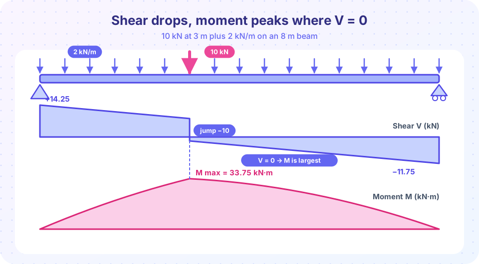
Example 3: both loads together
Span 8 m, a 10 kN point load at x = 3 m, and a uniform 2 kN/m load over the whole span (total 16 kN). Moments about A: By × 8 = 10 × 3 + 16 × 4 = 94, so By = 11.75 kN and Ay = 26 − 11.75 = 14.25 kN.
| Region | V(x) |
M(x) |
|---|---|---|
0 < x < 3 |
14.25 − 2x |
14.25 x − x² |
3 < x < 8 |
4.25 − 2x |
14.25 x − 10 (x − 3) − x² |
At x = 3 the shear drops from +8.25 to −1.75 (a jump of 10 kN), so it crosses zero right at the load. The maximum moment is there: M(3) = 42.75 − 9 = 33.75 kN·m. At x = 8: V = 4.25 − 16 = −11.75 = −By ✓ and M = 114 − 50 − 64 = 0 ✓.
This is how you superpose: the diagram of combined loads is the sum of the diagrams of each load alone, because the equations are linear. Check example 3 with examples 1-style point load (P = 10, a = 3) plus the uniform one: M_max of the pieces at x = 3 is 10 × 3 × 5/8 = 18.75 and 2 × 3 × 5 / 2 = 15. Their sum is 33.75 ✓.
Common misconceptions
"The maximum moment is always at midspan." Only for symmetric loading. It is where V = 0 or changes sign.
"Shear is zero where moment is zero." The opposite is more nearly true at the ends of a simply supported beam: the moment is zero but the shear is at its largest.
"A point load makes the moment jump." It makes the shear jump and the moment have a kink (a change of slope). Only an applied couple makes the moment jump.
Try it
Press Run (or Ctrl + Enter) to see the result here.
Program input · what you'd type while the program runs
Type the answers before you press Run, one per line. Each time the program reads a line (with input()), it gets the next line from this box.
Check your understanding
Quick check · 5 questions
of 5 answered You scored / 5 · perfect!
-
1. A simply supported beam of 10 m carries a uniform load of 4 kN/m. The maximum bending moment is:
M_max = w L² / 8 = 4 × 100 / 8 = 50 kN·m at midspan. -
2. A 20 kN point load acts at the middle of a 6 m simply supported beam. M_max =
M_max = P L / 4 = 20 × 6 / 4 = 30 kN·m. -
3. At a point load, the shear diagram:
A downward point load makes V drop by P (reading left to right). The moment has the kink, not a jump. -
4. Where does the maximum bending moment occur?
Because dM/dx = V, M has a maximum or minimum where V passes through zero. -
5. Which loads make the moment diagram jump?
A couple adds directly to the internal moment, so M jumps by the couple's value.
Summary
- Split the beam into regions; write
V(x)andM(x)for each. M_maxoccurs whereV = 0(or changes sign). Check both ends of each region.- Standard maxima: central point load
PL/4, uniform loadwL²/8. - Diagrams of separate loads can be added (superposition).
Track your progress
Create a free account to tick off lessons and pick up where you left off on any device.
of Engineering Statics lessons completed