


















Lesson 27 of 46 · Noise and Error Performance
Thermal Noise and Noise Figure
Compute the thermal noise floor kTB and -174 dBm/Hz, define noise figure and noise temperature, and use the Friis formula to see why the first amplifier matters most.
Every resistor above absolute zero hums with random voltage. The electrons inside jiggle with thermal energy, and the jiggling produces a tiny fluctuating voltage across the terminals. It was measured by John Johnson at Bell Labs in 1926 and explained by Harry Nyquist in the same year, so it is called Johnson-Nyquist noise, or just thermal noise. In a receiver this noise is the baseline against which every signal competes.
Once you know the noise floor of an ideal receiver, a second question follows: how much extra noise do real amplifiers, mixers and cables add? The answer is the noise figure, and the Friis cascade formula tells you which stage deserves your design effort.
What you will learn
- Compute thermal noise power
N = k·T·Band know the anchor value−174 dBm/Hz. - Compute the open-circuit noise voltage of a resistor.
- Define noise factor and noise figure, and convert to noise temperature.
- Use the Friis formula for a cascade.
- Explain why a low-noise amplifier goes first.
Key terms
- k: Boltzmann constant,
1.380649 × 10⁻²³ J/K. - T0: the standard reference temperature, 290 K.
- Noise factor F: SNR at the input divided by SNR at the output; noise figure
NF = 10·log10(F)in dB. - Equivalent noise temperature Te:
Te = T0·(F − 1); the temperature of an input resistor that would produce the same added noise. - LNA: low-noise amplifier.
Thermal noise power
A resistor at temperature T kelvin delivers at most the following noise power to a matched load in bandwidth B hertz:
N = k · T · B
The open-circuit RMS noise voltage across resistance R is v = √(4·k·T·R·B). For R = 50 Ω, T = 290 K and B = 1 MHz, that is √(4 × 1.38×10⁻²³ × 290 × 50 × 10⁶) ≈ 0.9 µV, so small that it is invisible in everyday electronics, but communications signals can be just as small.
Notice what is missing: the formula does not depend on the resistance value for the power. Noise power depends only on temperature and bandwidth, which is why the noise floor can be written as a density. At T0 = 290 K:
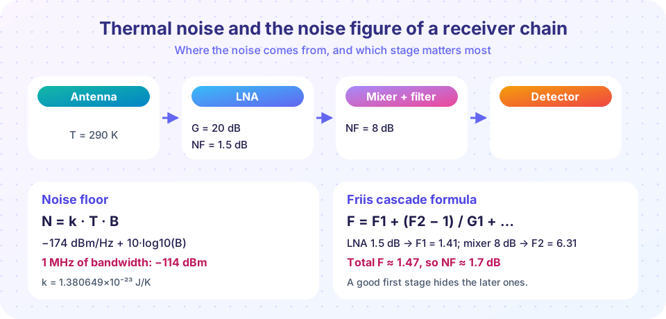
N0 = k·T0 = 4.0 × 10⁻²¹ W/Hz = −174 dBm/Hz
Then for any bandwidth: N(dBm) = −174 + 10·log10(B in Hz). A 1 MHz channel has −174 + 60 = −114 dBm. A 20 MHz Wi-Fi channel has −174 + 73 = −101 dBm before the receiver adds anything of its own.
Noise figure
Real receivers add noise. The noise factor compares signal quality going in with signal quality coming out:
F = SNR_in / SNR_out ≥ 1, and NF = 10·log10(F) dB.
A perfect noiseless amplifier has NF = 0 dB. A good low-noise amplifier at microwave frequencies is below 1 dB, an ordinary receiver is 3 to 10 dB. The noise of a receiver with noise figure NF and bandwidth B referred to its input is
N_total = −174 dBm/Hz + 10·log10(B) + NF
Equivalently, the receiver behaves as a noiseless device preceded by an extra noise source at temperature Te = T0·(F − 1). Satellite and radio-astronomy engineers prefer noise temperature because it adds directly: T_sys = T_antenna + T_receiver.
The Friis formula for cascades
For stages with noise factors F1, F2, F3 and available power gains G1, G2 (in linear units, not dB):
F_total = F1 + (F2 − 1)/G1 + (F3 − 1)/(G1·G2) + …
Read it as: the noise of stage 2 is divided by the gain that came before it. Noise that enters late in the chain meets a signal that has already been amplified, so it matters less. Noise from the first stage is not divided by anything.
Example: an LNA with G1 = 20 dB (a factor 100) and NF1 = 1.5 dB (F1 = 1.41) feeds a mixer with NF2 = 8 dB (F2 = 6.31). Then F = 1.41 + (6.31 − 1)/100 = 1.47, so NF ≈ 1.7 dB: almost all of it is the LNA. Swap the order, with the mixer (gain 10 dB) first, and the same two parts give about 8 dB. Same parts, much worse receiver.
Lossy parts matter the same way. An attenuator of loss L (linear) has F = L at room temperature, so a cable with 3 dB loss in front of an LNA adds 3 dB to the noise figure. That is why microwave dishes mount the LNA at the feed, not at the bottom of a long cable.
Common misconceptions
- "Thermal noise power depends on the resistance." The available power is
kTB, independent ofR; only the voltage depends onR. - "A 3 dB noise figure means the signal loses 3 dB." It means the output SNR is 3 dB lower than the input SNR; the signal itself may even be amplified.
- "Add noise figures in dB across stages." Cascades need the Friis formula in linear units.
- "Narrowing the filter after the LNA reduces the noise figure." A narrower bandwidth lowers the total noise power, but the noise figure of each stage is unchanged.
Try it
First, a noise-floor calculator. Change the bandwidths or the temperature to see the effect.
Press Run (or Ctrl + Enter) to see the result here.
Program input · what you'd type while the program runs
Type the answers before you press Run, one per line. Each time the program reads a line (with input()), it gets the next line from this box.
Second, a Friis calculator with a plot of how the total noise figure of the chain from the figure responds to the LNA gain.
Press Run (or Ctrl + Enter) to see the result here.
Program input · what you'd type while the program runs
Type the answers before you press Run, one per line. Each time the program reads a line (with input()), it gets the next line from this box.
Check your understanding
Quick check · 5 questions
of 5 answered You scored / 5 · perfect!
-
1. What is the thermal noise power in a 10 MHz bandwidth at 290 K?
−174 dBm/Hz + 10·log10(10⁷) = −174 + 70 = −104 dBm. -
2. A receiver has a noise figure of 5 dB. In a 1 MHz bandwidth, what noise power does it present at its input, relative to its input terminals?
−174 + 60 + 5 = −109 dBm. -
3. In the Friis formula, why does the second stage matter less than the first?
The (F2 − 1)/G1 term shrinks as the first-stage gain G1 grows. -
4. A coaxial cable with 2 dB loss sits between the antenna and the LNA. Roughly how does it change the system noise figure?
A passive loss at room temperature has noise factor equal to its loss, so it adds directly in front of the LNA. -
5. Which formula gives the available thermal noise power?
Available power is kTB; 4kTRB is the mean-square open-circuit voltage.
Summary
- Thermal noise power is
N = kTB; at 290 K the density is−174 dBm/Hz. - Noise figure
NF = 10·log10(F)measures the extra noise an element adds;Te = T0(F − 1). - Friis:
F = F1 + (F2 − 1)/G1 + …, in linear units; the first stage dominates. - Put a low-noise, high-gain stage first and keep losses ahead of it small.
Track your progress
Create a free account to tick off lessons and pick up where you left off on any device.
of Communication Systems lessons completed