


















Lesson 77 of 125 · Designing Databases
Entity-Relationship Modeling
Learn entity-relationship modeling. Read and draw ER diagrams, understand cardinality and crow's-foot notation, and turn a diagram into real SQL tables.
Before anyone writes CREATE TABLE, someone has to decide what the database should remember: which things exist, what you need to know about each one, and how they are connected. Entity-relationship (ER) modeling is the standard way to answer those questions on paper (or a whiteboard) before they harden into tables that are painful to change.
An ER diagram is a picture of that answer. It shows boxes for the things your system cares about and lines for the relationships between them, with small symbols that say "exactly one", "zero or more" and so on. Developers, analysts and business people can all read it, which makes it the cheapest place to catch a design mistake.
In this lesson you'll learn the vocabulary (entities, attributes, relationships, cardinality), read the two most common notations, model a small conference system, and translate the diagram into SQLite tables you can run.
Entities and attributes
An entity is a kind of thing your system needs to store facts about: a customer, a product, a talk, a room. Each individual thing (the customer Maya Fischer, the room Hall B) is an instance, and in the finished database each instance becomes one row. Entities are usually nouns, named in the singular in diagrams ("attendee") and often in the plural as tables (attendees).
An attribute is one fact about an entity, such as an attendee's name or email. Attributes come in a few flavors, and each flavor maps to tables differently:
| Kind | Example | What it becomes |
|---|---|---|
| Simple | email |
One column |
| Composite | address (street, city, postal code) |
Several columns |
| Multi-valued | phones (an attendee may have several) |
A separate table |
| Derived | talk_count (can be counted) |
Usually not stored; computed by a query or view |
| Key | id |
The primary key |
A key attribute identifies each instance uniquely. You'll see it underlined in one notation and marked PK in the other:
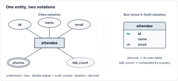
Chen notation (named after Peter Chen, who introduced ER modeling in 1976) draws entities as rectangles, attributes as ovals and relationships as diamonds. It is great for teaching concepts but takes a lot of space. Box notation, usually paired with crow's-foot line ends, lists the attributes inside the entity box like a table. Almost every database design tool uses the box style, so that's what the rest of this lesson uses.
Relationships and cardinality
A relationship connects entities: a speaker presents a talk, a talk is held in a room. Name relationships with verbs so you can read each line as a sentence in both directions.
The most important property of a relationship is its cardinality: how many instances on one side can be linked to one instance on the other side. There are three basic shapes:
- One-to-one (1:1). An attendee receives at most one badge, and each badge belongs to exactly one attendee.
- One-to-many (1:N). A room hosts many talks, but each talk is held in one room. This is by far the most common shape.
- Many-to-many (M:N). An attendee registers for many talks, and each talk has many attendees.
Cardinality has two halves. The maximum (one or many) decides the table structure. The minimum (zero or one), also called participation or optionality, says whether the link is required: must every talk have a room, or can a talk be scheduled before a room is assigned? Crow's-foot notation draws both halves at each end of the line:
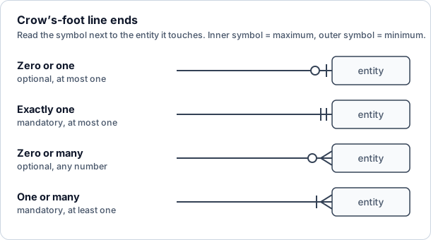
Here's the trick for reading a line: stand on the entity at the far end and read the symbols next to the entity you're looking at. For a line between talk and room with "exactly one" at the room end, you say: "each talk is held in exactly one room."
Other notations exist. UML class diagrams write the same facts as numbers (1, 0..1, 0..*, 1..*), and some tools print 1 and N (or M) on the lines. They all express the same two numbers, so once you understand minimum and maximum you can read any of them.
Modeling a conference
Let's model a small tech conference. After talking to the organizers, you write down the rules in plain sentences first. This step matters more than the drawing:
- A speaker presents one or more talks. A talk has one or more speakers (panels have several).
- A talk is held in exactly one room. A room can host any number of talks, including none.
- An attendee can register for any number of talks, and a talk can have any number of attendees.
- An attendee receives at most one badge, and every badge belongs to exactly one attendee.
Each noun became an entity and each verb became a relationship. Here is the conceptual model, which shows the ideas without worrying about how they'll be stored:
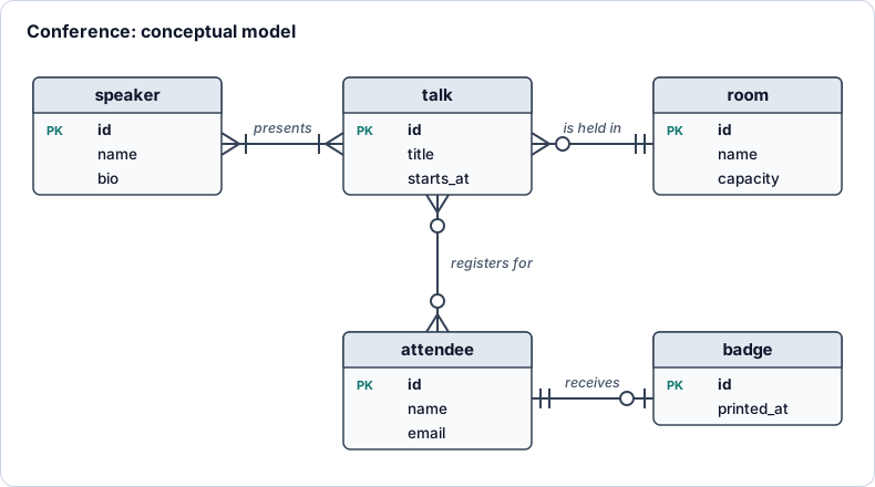
Read each line out loud in both directions and check it against the rules. "Each room hosts zero or many talks; each talk is held in exactly one room." If a sentence sounds wrong to the organizers, the diagram is wrong, and fixing a diagram costs nothing.
From diagram to tables
Turning an ER diagram into tables (the logical model) follows a few mechanical rules:
| In the diagram | In the database |
|---|---|
| Entity | A table; the key attribute becomes the primary key |
| Simple / composite attribute | One column / several columns |
| Multi-valued attribute | A separate table with a foreign key back to the owner |
| Derived attribute | Nothing stored; compute it with a query or a view |
| One-to-many | A foreign key column on the many side |
| Minimum of one on the "one" side | That foreign key is NOT NULL |
| One-to-one | A foreign key with a UNIQUE constraint |
| Many-to-many | A junction table holding two foreign keys |
The many-to-many relationships are the interesting part. A table column holds one value, so neither talks nor attendees can store "all my partners". Instead, the relationship itself becomes a table: each row of registrations says "this attendee registered for this talk". The pair of foreign keys is the primary key, so nobody registers twice for the same talk. The junction table is also the natural home for facts about the relationship rather than either entity, such as when the registration happened or a speaker's role on a panel.
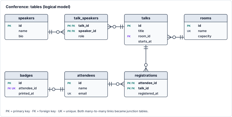
Notice what changed. The two many-to-many lines turned into two one-to-many lines each, meeting at a junction table. The 1:N relationship to rooms became a room_id column in talks. The 1:1 relationship became a unique attendee_id in badges. Also, "one or many speakers" became "zero or many" rows in talk_speakers: a plain foreign key can't force a talk to have at least one speaker, so rules like that end up in application code or triggers.
Here is the whole design as SQL. Run it, then query it:
Press Run (or Ctrl + Enter) to see the result here.
The panel appears three times because it has three speakers: that's the junction table doing its job. Ines Moreau appears twice because she has two talks. Try adding a fifth talk with no speakers and notice that the inner joins hide it; a LEFT JOIN would keep it.
One-to-one: a unique foreign key
A one-to-one relationship is a one-to-many relationship with the "many" taken away, and UNIQUE is how you take it away. The badge table points to its attendee, and the unique constraint stops a second badge for the same person. The last statement in this example fails on purpose:
Press Run (or Ctrl + Enter) to see the result here.
The LEFT JOIN shows the "zero or one" side: Kenji has no badge yet, so his printed_at is NULL. The final insert stops with Error: UNIQUE constraint failed: badges.attendee_id.
Why not put the badge columns straight into attendees? You often should. Split a 1:1 relationship into two tables only when there's a reason: the second part is optional and mostly empty, it's large and rarely read (a photo, a long biography), it has different access rules (salary data), or it has its own life cycle (a badge can be reprinted).
Many-to-many with relationship attributes
The registrations junction table records who signed up for what, and when. That timestamp belongs to neither the attendee nor the talk: it describes the pairing. Because the composite primary key covers both columns, a duplicate registration is rejected automatically:
Press Run (or Ctrl + Enter) to see the result here.
The keynote has 3 registrations and the other two talks have 1 each. The same junction table answers questions from both directions, which is exactly what the two crow's feet in the diagram promised. You'll build much more of this in One-to-Many and Many-to-Many.
Multi-valued attributes and weak entities
A multi-valued attribute like "phone numbers" is tempting to squeeze into one text column ('+1 555 0100, +1 555 0199'). Don't: you can't index, validate or search individual numbers properly, and the Normalization lesson calls this a first normal form violation. Give it its own table instead.
That new table is a weak entity: a phone number row means nothing without its attendee, so its key includes the owner's key. Diagrams often draw weak entities with a double border. In SQL, the giveaway is a composite primary key that starts with a foreign key:
Press Run (or Ctrl + Enter) to see the result here.
Recursive relationships
A relationship can connect an entity to itself. An employee reports to another employee; a talk can be a follow-up of an earlier talk; a category can have a parent category. In a diagram this is a line that leaves a box and comes back to it. In tables, it's a foreign key that references its own table:
CREATE TABLE employees (
  id INTEGER PRIMARY KEY,
  name TEXT NOT NULL,
  manager_id INTEGER REFERENCES employees (id)  -- NULL for the top of the tree
);
The company sample database uses exactly this design. You query it with self joins for one level and recursive CTEs for the whole tree.
Reading a diagram back from a database
You can also go the other way: start from an existing database and reconstruct its diagram. That's what "reverse engineering" in design tools does, and you can do it by hand with SQLite's pragmas. PRAGMA foreign_key_list shows every line of the diagram that leaves a table:
Press Run (or Ctrl + Enter) to see the result here.
Four foreign keys come back. Together they tell you that order_items is a junction table between orders and products (with quantity and unit_price as relationship attributes), that each order belongs to one customer, and that each product belongs to one category. Draw those as boxes and lines and you have the shop's ER diagram.
Good habits and common mistakes
- Write the rules as sentences first. "Each X has exactly one Y" is easy for non-developers to confirm or reject.
- Model the business, not the screens. A form that shows a customer with their last order doesn't mean "last order" is an attribute of a customer.
- Watch for hidden many-to-many relationships. If you catch yourself adding
tag1,tag2,tag3columns, you need a junction table. - Don't store derived data by default. A stored
talk_countcan drift away from the real count. Compute it, and only cache it later if performance requires it. - Ask about history. "A talk is held in one room" might really mean "one room at a time". If rooms can change and you must remember old assignments, that's a separate entity.
- Keep the diagram next to the code. Text-based diagram tools (where you describe tables in a small language and the tool draws them) let you version the diagram with your migrations.
Check your understanding
Quick check · 5 questions
of 5 answered You scored / 5 · perfect!
-
1. A course has exactly one teacher, and a teacher can teach many courses. Where does the foreign key go?
In a one-to-many relationship the foreign key goes on the "many" side. Each course row stores its single teacher's id; a teacher row can't hold a list of courses. -
2. In crow's-foot notation, what does a circle followed by a crow's foot next to an entity mean?
The circle is the minimum (zero) and the crow's foot is the maximum (many), so the link is optional and unlimited. -
3. How do you turn a many-to-many relationship between students and clubs into tables?
A junction table stores one row per pairing. Lists in a text column or numbered columns can't be indexed or constrained properly and break as soon as someone joins a fourth club. -
4. Which constraint turns a one-to-many relationship into a one-to-one relationship?
WithUNIQUE, each parent row can be referenced at most once, so the "many" side can hold at most one matching row.NOT NULLonly controls the minimum. -
5. An
ageattribute can always be calculated frombirth_date. What kind of attribute is it, and what should you usually do with it?Derived attributes can be computed from other data. Storing them means they can go stale (an age is wrong a year later), so compute them when you read the data.
Summary
- ER modeling describes entities (things), their attributes (facts) and the relationships between them before you create tables.
- Cardinality has a maximum (one or many) and a minimum (zero or one). Crow's-foot notation draws both at each line end; the symbol touching the entity is the maximum.
- Write the business rules as sentences and read every line of the diagram back in both directions.
- Mapping rules: entity → table, 1:N → foreign key on the many side, 1:1 → unique foreign key, M:N → junction table, multi-valued attribute → its own table, derived attribute → computed.
- Junction tables can carry attributes of the relationship itself, such as a registration date or a role.
pragma_foreign_key_listlets you rebuild a diagram from an existing SQLite database.
Next: Normalization, where you'll learn the rules that tell you whether a table design will cause trouble later.
Track your progress
Create a free account to tick off lessons and pick up where you left off on any device.
of SQL lessons completed